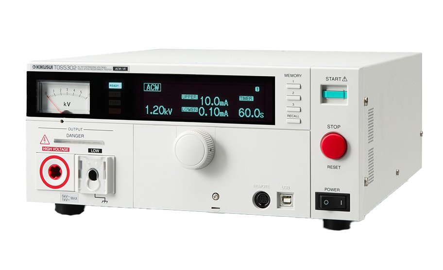
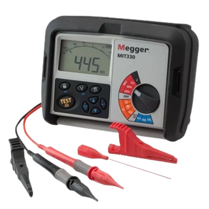
Flash testing: Distinctions & Clarification
Distinguishing between main circuits and auxiliary circuits is crucial for ensuring proper operation, safety, and compliance. Both circuit types serve distinct roles and require different testing methods. This post outlines these differences, explains why a 2,500V AC Power-Frequency Withstand Voltage Test (Flash Test) is used for main circuits, and highlights exceptions for sensitive components, including Automatic Transfer Switches (ATS) and Air Circuit Breakers (ACBs). Key clauses from BS EN 61439-1 are referenced to provide clarity and traceability. Additionally, we explore the importance of conducting these tests both in the factory and on-site after reassembly.
Personally flash testing has been a grey art obfuscated by time / whispers and passed down experience. This article delves a bit deeper into the regs, origin and history. Plus justification and clauses in relation to 61439-1.
Main Circuits: The Backbone of Power Distribution
Main circuits carry the primary electrical power within a system, distributing it from the supply source to various loads. These circuits handle the system’s full rated current and voltage, making them essential to the system’s safety and functionality.
Typical Components of Main Circuits:
- Incoming Isolators or Switch Disconnectors
- Main Circuit Breakers (MCBs, MCCBs, ACBs)
- Busbars
- Power Cables
- Outgoing Circuit Breakers
- Main Contactors
- Automatic Transfer Switches (ATS)
Testing Requirements for Main Circuits
Main circuits are tested using a Power-Frequency Withstand Voltage Test (Flash Test) as outlined in Clause 10.9 of BS EN 61439-1.
- Standard Test Voltage: 1,890V AC for systems rated between 300V and 600V (Table 10.9.2).
- Test Duration:
- 60 seconds during type testing (per BEAMA guidance for dielectric tests and Clause 10.9.4).
- 1 second during routine testing (per Clause 10.10.2 for installed or maintained systems).
Why Use 2,500V AC for Power-Frequency Withstand Voltage Tests?
Although BS EN 61439-1 specifies a minimum test voltage of 1,890V AC, testing at 2,500V AC aligns with industry best practices and provides additional safety margins. This approach also references historical standards like BS 60439-1:1985, where 2,500V AC was the standard test voltage for systems with rated insulation voltages between 300-600V. The timing went from 60 seconds down to 5 now it is stated as 1 seconds in 61439-1. Please carry on reading though as 61439-1 is a guideline. Being the manufacturer we have an opinion and have justification for selecting certain test criteria. One main point is that the voltage applied is not immediate but a rise. We typically select 2 seconds for a ramp up and the 60. The BEAMA page mentions +/- 2 Seconds.
As a logical rule Clause 11.9 specifies that during this test, the circuit under evaluation must sustain the applied voltage without experiencing a leakage current exceeding 3.5mA. This threshold ensures the integrity of the insulation while allowing for minor, acceptable leakage currents inherent in normal operation.
The 3.5mA limit is vital as it provides a balance between detecting insulation faults and accounting for natural leakage through capacitive components. This value is part of the routine testing procedure for all main and auxiliary circuits undergoing dielectric testing, ensuring compliance with international safety and performance standards. IF you get a fail I would seriously take a look at your clearance and for any damage to the fabric of the board.

2500VAC Reasoning in relation to diverging away from the suggested table of 1890V. This being for FACTORY tests. Meaning new initial test and re-assembly test on SITE (See Factory and On-Site Testing) paragraph.
Test Voltage = (2 × Ui) + 1,000V
Where:
- Ui is the rated insulation voltage (e.g., 400V for most low-voltage systems).
For a 400V system:
- Test Voltage = (2 × 400V) + 1,000V = 1,800V AC
To enhance safety and reliability, the industry rounds up to 2,500V AC for main circuits. This provides additional benefits:
1. Enhanced Safety for Overvoltage Conditions
Main circuits must withstand transient overvoltages from:
- Lightning strikes
- Switching surges
- Power supply fluctuations
Testing at 2,500V AC ensures the system can endure these extreme conditions in compliance with Clause 10.9.1.2.
2. Accounting for Insulation Ageing
Over time, insulation degrades due to:
- Humidity
- Temperature fluctuations
- Dust and contaminants
A higher test voltage provides a safety margin, ensuring reliable performance even as insulation ages, as covered in Clause 10.9.3.2.
3. Industry Standardisation and Best Practices
Testing at 2,500V AC is widely adopted, offering consistency across projects and exceeding minimum regulatory standards.
4. Assuring Reliability for Critical Infrastructure
In environments such as hospitals, data centres, or industrial facilities, reliability is paramount. Testing at 2,500V AC ensures these systems perform safely under all conditions, as reinforced by Clause 8.2.2 for verification procedures.
Factory and On-Site Testing
Conducting dielectric tests both in the factory and on-site after reassembly ensures insulation integrity throughout the lifecycle of the equipment. This dual testing approach verifies that no damage occurred during transportation or handling between the workshop and site.
On-site testing is crucial for identifying any issues caused by mechanical stress, environmental factors, or improper reassembly. By comparing the results of factory and on-site tests, any deviations beyond acceptable tolerances can be quickly identified and rectified, providing confidence in the system’s safety and performance.
This process ensures compliance with Clause 10.10.3, which mandates insulation testing after installation or maintenance.
Auxiliary Circuits: Supporting Functions
Auxiliary circuits manage control, signalling, and monitoring, operating at lower voltages and current levels. These circuits provide essential feedback and automation to support main circuits.
Typical Components of Auxiliary Circuits:
- Control Relays
- Pilot Lights and Indicators
- Push Buttons and Switches
- Protection Relays
- Sensors and Alarms
- Communication Devices (e.g., Ethernet modules)
Auxiliary circuits often play a crucial role in system automation, monitoring, and control.
Defining Auxiliary Circuits
Auxiliary circuits are defined in Clause 11.9 of BS EN 61439-1 as circuits that:
- Are not main circuits.
- Typically operate below 16A and can often be tested using functional testing methods.
Special Consideration for Circuits Above 16A
Circuits above 16A, even if they serve an auxiliary function, are treated as main circuits under BS EN 61439-1. These circuits must undergo a Power-Frequency Withstand Voltage Test (Flash Test) unless they contain sensitive electronic elements. For such circuits:
- Without Electronics: Perform a flash test as per the main circuit guidelines.
- With Electronics: Conduct a 500V DC Insulation Resistance Test to avoid damaging the sensitive components.

What is a Functional Test?
A functional test ensures that auxiliary circuits operate correctly under their rated operational voltage. This type of test is often used for circuits below 16A to verify performance without subjecting them to high-voltage dielectric tests.
Key Aspects of Functional Testing
- Verification of Circuit Operation: The test involves supplying the circuit with its normal operating voltage to confirm that all components, such as relays, indicators, and sensors, function as intended.
- Application: Functional testing is sufficient for auxiliary circuits covered under Clause 11.9.2 of BS EN 61439-1.
- Exemption from Flash Testing: Circuits that pass a functional test do not require a Power-Frequency Withstand Voltage Test, as their operational safety is demonstrated under normal working conditions.
ACBs and ATS Units: Special Considerations
Both Air Circuit Breakers (ACBs) and Automatic Transfer Switches (ATS units) combine mechanical power-handling components and sensitive electronic protection or control units. These electronic components are integral to the devices, managing key functions like monitoring, protection, and automatic operation.
Why These Devices Are Sensitive
- Integrated Electronics:
Many ACBs and ATS units include sealed electronic modules that cannot be removed without voiding the warranty. - Risk of Damage During Flash Testing:
Applying a high-voltage flash test directly to the entire device can cause irreparable damage to the electronics.
Manufacturer Testing Evidence
Both ACBs and ATS units undergo comprehensive type testing by the manufacturer to ensure compliance with BS EN 61439-1. This includes testing the combined performance of mechanical and electronic systems under controlled conditions.
Best Practice for On-Site Testing
- Rely on Manufacturer’s Evidence:
Retain and reference the manufacturer’s test certificates as proof of compliance with Clause 8.2.2.6. This evidence eliminates the need for further flash testing of the sensitive electronics on-site. - Perform Functional and Visual Inspections:
- Conduct a functional test to verify correct operation under normal working conditions.
- Carry out a visual inspection to detect any physical damage or faults.
- Insulation Resistance Testing:
Where possible, apply a 500V DC Insulation Resistance Test to external cabling and non-electronic elements of the circuit. This ensures overall system integrity without exposing sensitive components to high test voltages.
Relevant BS EN 61439-1 Clauses for Reference
| Clause | Description |
|---|---|
| Clause 10.9 | Power-Frequency Withstand Voltage Test requirements for main circuits. |
| Table 10.9.2 | Specifies test voltages for systems based on their rated insulation voltage. Please see aforementioned 2500VAC passage for deviation justification. |
| Clause 11.1 | Routine verification, including insulation testing for installed equipment. |
| Clause 11.9 | Insulation and functional testing requirements for auxiliary circuits. |
Key Points for Project Managers
- Main Circuit Testing
Applying a 2,500V AC Power-Frequency Withstand Voltage Test provides an enhanced safety margin, ensuring the system can handle overvoltage events and long-term insulation ageing. - Auxiliary Circuit Testing
Circuits above 16A, even if they serve an auxiliary function, are treated as main circuits under BS EN 61439-1. These circuits must undergo a Power-Frequency Withstand Voltage Test (Flash Test) unless they contain sensitive electronic elements. - Factory and On-Site Testing
Conducting dielectric tests both in the factory and on-site after reassembly ensures insulation integrity, identifies potential damage during transit, and provides confidence in long-term performance. - Handling Sensitive Devices
For components like ATS units, PLCs, and ACBs, testing strategies must protect sensitive electronics. Manufacturer test results, combined with on-site functional checks, ensure compliance without compromising warranty or device integrity.
Ensuring Safety and Reliability
Distinguishing between main and auxiliary circuits is key to applying the correct testing methods. While Power-Frequency Withstand Voltage Testing at 2,500V AC offers robust protection for most main circuits, alternative tests like Insulation Resistance Testing safeguard sensitive components such as ATS units and ACBs.
Conducting these tests both in the factory and on-site ensures compliance with BS EN 61439-1, while providing peace of mind for customers and approaching contractors.
Relevant Reading
Flash Testing vs. Insulation Resistance Testing: What Is the Difference?
Disclaimer:
The information provided on this site is for general informational purposes only and may not reflect the most current regulations or standards. Legislation, industry guidelines, and best practices can change over time, and it is the user’s responsibility to research and ensure compliance with the latest requirements for their specific situation. Always consult a qualified professional for advice tailored to your project or application.
